¡ Por fin sabemos de donde saca MediaMarkt esos precios !

Bueno, es un decir, porque algunas cosas en MediaMarkt son caras de la ostia… Pero bueno, era una buena entradilla para el post. Y es que parece que han puesto a tres orangutanes redactando la publicidad. Atentos:

Hoy me llega a casa el folleto de publi más jodidamente grande que he visto en mi vida. Si los normales de MediaMarkt ya son enormes, imaginaos uno con EL DOBLE de tamaño. Supongo que es para festejar que tienen una LG FullHD de 47” a 799 lereles. El caso es que, cuando más han querido llamar la atención con un folleto donde todo España pondrá sus miradas a la caza de una ganga, va y te encuentras esto:

mmrkt

Vaya pedazo de patada el diccionario de la Royal Academy. Ya me veo la escena…

- Pacoooo!, ¿como se escribe eso de “mobail”?

- A ver, ignorante de la vida… ¿Cómo quieres que se escriba? ¡PUES COMO SUENA!

¡Qué grande! En mayores letras no lo podían haber puesto. A ver si después de tantos años, lo de la “E” de MediaMarkt va a ser otra de estas… Juas!

Actualizar el Firmware de un LGRH177

En muchos sitios se dice cómo hacer esto, pero casi todos se dejan un punto fundamental (el 3B) que hace que el dvd no reconozca el disco como de actualización. Pongo las instros en inglés, porque son casi las 2 de la mañana y me da pereza traducirlas:

1) Go to link: http://pl.lgservice.com/
2) press Floppy disc icon
3) select DVD/Video in Produkt
4) press Szukaj
5) select the file from the list

--[Creating the CD by using NERO]
1) use a CD-R or CD-RW;
2) create an ISO CD-ROM with only one session;
3) use ISO-9660 mode;
3b) select 31characters file name length;
4) label CD as "RH1000_UP";
5) burn just the file LG_HDR_UPDATE.004;
6) burn with DAO (disc-at-once) mode and finalize;
7) insert the CD in the DVD-Recoder;
8 ) press "Home" button and go on "Music > Disc"
9) follow the instruction the recorder shows (... you
have to press some times REC and so on..)
10) after the upgrade has been completed (be sure of this!), turn off the recorder.

A disfrutar!

Arreglar un DVD LGRH177 con lector/grabador defectuoso

Si eres uno de los afortunados (o desafortunados, según se mire) poseedores de un dvd grabador LGRH177 sigue leyendo, esto te interesa.

Eres afortunado porque el cacharrillo está bastante bien, pero la fortuna se te acabará, tarde o temprano. Estos bichos cascan más que una escopeta de feria, sobre todo la unidad lectora/grabadora de discos.

Lo primero de todo, algunos trucos para este dvd y los de series parecidas: como saber qué firmware tienes, como actualizarlo, etc etc.

Lo segundo de todo, comentarte que muy probablemente, alguna vez este dvd te de un error al leer o escribir un DVD. Siento decirte que la frecuencia con la que falla va a aumentar, hasta que deje de funcionar del todo. Y sin un DVD donde grabar las cosas, o desde donde meter pelis al disco duro, de poco nos sirve el invento. ¿La solución?

Cambiar la unidad de DVD

[Note: If you don´t undestand Spanish, here you will find a good english explanation about this procedure]

Sí, has oído bien. Es tan fácil que no entiendo como hay tanta gente por cientos de foros de todo el mundo pidiendo ayuda para reparar su bichito. Si abrís la carcasa, os encontraréis que dentro es muy muy parecido a un PC. El disco duro es, obviamente, un disco IDE normal y corriente. Y el lector de DVD, pues más de lo mismo: un lector normal y corriente de ordenador. Esto es lo que os vais a encontrar al abrirlo (perdón por la calidad de las fotos, son de móvil):

SNC00153

Como véis (aunque en la foto no se vea bien), ambos dispositivos van conectados con cable IDE. Desmontad con mucho cuidado el lector de DVD (el cable que trae el reproductor es muy muy fino y se rompe con facilidad).

Una vez hayáis extraído el lector, desmontadle la carcasa metálica que trae, e id a la tienda a por un sustituto. Yo he usado una grabadora de DVDs que tenía por ahí, por casualidad también marca LG, aunque esto no creo que importe nada. Obviamente, la grabadora que escojáis ha de ser IDE. No seáis muñones y vayáis a comprar una SATA. En concreto, el modelo que yo he probado y que os puedo asegurar funciona es este:

SNC00161

Aseguraos de poner el Jumper de la grabadora en modo “Master” y desmontad la carcasa de ésta también, quitándole también todo el frontal y el embellecedor de la bandeja, ya que en el LG molestarían. Una vez tenemos las dos unidades “en pelotas” veremos que son casi idénticas (ambas fabricadas por Panasonic):

SNC00158

Solo vais a encontrar una complicación. La unidad que viene en el RH177 es 4mm más delgada que las unidades estándar. Por culpa de esto, tendremos que hacer un par de ñapas para encajar la nueva, poniéndole a la nueva unidad parte de la carcasa metálica antigua, y parte de la nueva.


Como el lector tiene que ir un pelín más alto que la base del reproductor, es conveniente utilizar la parte inferior de la carcasa metálica original del RH177, mientras que para la parte superior, es mejor usar la de la carcasa de la unidad nueva (ya que la original del RH no te va a encajar).

SNC00162

Mitad inferior de la carcasa RH177

SNC00159

Mitad superior de la carcasa del lector sustituto

Así, hacemos un pequeño Frankenstein con las carcasas, pero queda fetén. Para que encaje la parte inferior en la nueva unidad, es posible que tengas que empujar un poco hacia adentro el LED de actividad. En mi caso molestaba un poco.

Un par de últimos detalles: una vez tenemos la nueva unidad con ambas partes de las carcasas encajadas, vamos a tener que doblar algunas cosas para que todo encaje. Si si… doblar.

1.- En la carcasa del nuevo lector, la parte inferior tendrá unas pestañas que nos van a molestar. Doblarlas hacia arriba hasta que los agujeritos de las patas se alineen bien con los de la base.

2.- Veremos que, dado que la nueva unidad es más ancha, no cabe en la carcasa principal del DVD. Para lograr que entre bien, tenemos que doblar una pestaña del frontal de dicha carcasa. Parece una burrada pero no nos va a molestar en absoluto después. Os muestro en la siguiente foto qué teneis que doblar y como (en rojo):

SNC00154_2

3.- Por último, es muy fácil que la nueva unidad no os quede perfectamente alineada con la posición original, y que eso haga que la bandeja no salga bien (pegará con los embellecedores del DVD una vez montado todo). Para solucionarlo, en mi caso bastón con quitarle la puertecilla embellecedora al frontal del DVD, que le restaba mucho espacio. Sin ella, queda muy jujano, pero qué quieres que te diga. De tener que tirar el cacharro a la basura a que funcione de nuevo al 100%…

¿Y qué pasa con el disco duro?

Pues más de lo mismo.

Si se te ha estropeado o si simplemente quieres uno de más capacidad, es muy fácil cambiarlo. Yo no lo he hecho, pero hay instrucciones por la red acerca del procedimiento.

Os dejo un recurso muy valioso acerca del RH177. Tiene mil tutoriales de todo tipo, incluso sobre algo que realmente eché de menos en este DVD: cómo instalarle una toma USB para acceder al disco: http://ifndef.altervista.org/

Increíble!!!!

Final de Microsoft Imagine Cup España 2009

El próximo 7 de Mayo, seré uno de los ponentes en la final del concurso Imagine Cup 09 en su edición Española, que tendrá lugar si no me equivoco en la Universidad Complutense de Madrid.

Se trata de un concurso internacional que promueve Microsoft para apoyar a los nuevos talentos desde la Universidad. Los premios van desde un smartphone o una XBox360 hasta un viaje a El Cairo con todos los gastos pagados para participar en la final mundial de Imagine Cup. Según la propia web:

“En la edición de Imagine Cup en España participan estudiantes universitarios españoles con inquietud por la tecnología y en particular por el desarrollo de aplicaciones innovadoras y creativas. La séptima edición internacional de Imagine Cup tiene como objetivo encontrar soluciones a los problemas reales de nuestros días.”

Más información haciendo click en la foto.

Collision detection in XNA

[This article continues the prelude about collision detection published here. It refreshes and completes the older Collision detection in XNA posts –parts I, II and III-, written a long time ago and which were demanded to be completed many times. Finally, here it is]

Simple Collision Detection

XNA includes simple intersection tests for shapes like: Bounding Spheres, AABB (Axis Aligned Bound Box), Planes, Rays, Rectangles, Frustums, etc, and any combination of them. And what is even more useful, 3D models already have bounding spheres for their parts.
Using those tests, almost any kind of game-like intersection can be achieved. You must remember that a Mesh-Whatever intersection is expensive (depending in the number of polygons, of course), and should be left for special cases in which a very high intersection accuracy is needed. So, it’s usually preferred to approximate a complex geometry by a bunch of spheres or boxes, than using the real triangles (see Part 1).
There´s a very good post at Sharky´s blog about XNA collisions, specially focused in approximating generic shapes with bounding spheres. You can find it here.

Accurate collision detectionDespacho_2_Low


As commented earlier, sometimes a more accurate intersection method is needed. For example, for lighting calculations (where tracing rays are the best and more usual approach to modeling lights –see pic on your right-), the Ray-Mesh intersection test seems to be the best option. In D3D, there´s a Mesh.Intersect method ready for you, that performs the desired intersection test, but in XNA, there´s not such a method, and we will have to do it on our own.
To do it, we will need a system-memory copy of the geometry. Unfortunately, meshes are usually created with the ReadOnly flag in XNA (to make their management fast), what won´t allow us to access their geometry at runtime. To do so, we´ll have to deal with Custom Content Processing.
Note: Here you will find and introduction to Custom Content Processing.

Implementing a Custom Content Processor for collision detection

The solution to the previous problem is to make a custom content processor that stores a copy of the geometry information at build time, where there´s still access to it. All the information needed will be stored in a new class we will name MeshData.
 public class MeshData
{
     public VertexPositionNormalTexture[] Vertices;
     public int[] Indices;
     public Vector3[] FaceNormals;
 
     public MeshData(VertexPositionNormalTexture[] Vertices, int[] Indices, Vector3[] pFaceNormals)
     {
         this.Vertices = Vertices;
         this.Indices = Indices;
         this.FaceNormals = pFaceNormals;
     }
}
 
You can put in here all the information you need. By the moment, it will be enough to store the vertices, indices and face normals.
When VisualStudio processes each model with our ContentProcessor, it will write the model´s data to an XNB file. When it finds a MeshData object, will search for a writer that is able to serialize it, so we have to write our custom ContentTypeWriter for the MeshData class:
[ContentTypeWriter]
public class ModelVertexDataWriter : ContentTypeWriter<MeshData>
{
    protected override void Write(ContentWriter output, MeshData value)
    {
        output.Write((int)value.Vertices.Length);
        for (int x = 0; x < value.Vertices.Length; x++)
        {
            output.Write(value.Vertices[x].Position);
            output.Write(value.Vertices[x].Normal);
            output.Write(value.Vertices[x].TextureCoordinate);
        }
 
        output.Write(value.Indices.Length);
        for (int x = 0; x < value.Indices.Length; x++)
            output.Write(value.Indices[x]);
 
        output.Write(value.FaceNormals.Length);
        for (int x = 0; x < value.FaceNormals.Length; x++)
            output.Write(value.FaceNormals[x]);
    }
 
    public override string GetRuntimeType(TargetPlatform targetPlatform)
    {
        return typeof(MeshData).AssemblyQualifiedName;
    }
    public override string GetRuntimeReader(TargetPlatform targetPlatform)
    {
        return "ContentProcessors.ModelVertexDataReader, ContentProcessors, Version=1.0.0.0, Culture=neutral";
    }
}
 
In a similar way, when the ContentPipeline tries to read back the XNB file, it will search for a deserializer for the type MeshData, so we have to write our own ContentTypeReader:
 public class ModelVertexDataReader : ContentTypeReader<MeshData>
{
     protected override MeshData Read(ContentReader input, MeshData existingInstance)
     {
         int i = input.ReadInt32();
         VertexPositionNormalTexture[] vb = new VertexPositionNormalTexture[i];
         for (int x = 0; x < i; x++)
         {
             vb[x].Position = input.ReadVector3();
             vb[x].Normal = input.ReadVector3();
             vb[x].TextureCoordinate = input.ReadVector2();
         }
 
         i = input.ReadInt32();
         int[] ib = new int[i];
         for (int x = 0; x < i; x++)
             ib[x] = input.ReadInt32();
 
         i = input.ReadInt32();
         Vector3[] normals = new Vector3[i];
         for (int x = 0; x < i; x++)
             normals[x] = input.ReadVector3();
 
         return new MeshData(vb, ib, normals);
     }
}
Finally, our Custom Content Processor that fills up the MeshData objects for each model that goes through it. Note: some parts taken from ZiggyWare
    [ContentProcessor(DisplayName = "Custom Mesh Processor")]
    public class PositionNormalTexture : ModelProcessor
    {
        public override ModelContent Process(NodeContent input, ContentProcessorContext context)
        {
            ModelContent model = base.Process(input, context);
            foreach (ModelMeshContent mesh in model.Meshes)
            {
                // Put the data in the tag.
                VertexPositionNormalTexture[] vb;
                MemoryStream ms = new MemoryStream(mesh.VertexBuffer.VertexData);
                BinaryReader reader = new BinaryReader(ms);
 
                VertexElement[] elems = mesh.MeshParts[0].GetVertexDeclaration();
                int num = mesh.VertexBuffer.VertexData.Length / VertexDeclaration.GetVertexStrideSize(elems, 0);
 
                vb = new VertexPositionNormalTexture[num];
                for (int i = 0; i < num; i++)
                {
                    foreach (VertexElement e in elems)
                    {
                        switch (e.VertexElementUsage)
                        {
                            case VertexElementUsage.Position:
                                vb[i].Position.X = reader.ReadSingle();
                                vb[i].Position.Y = reader.ReadSingle();
                                vb[i].Position.Z = reader.ReadSingle();
                                break;
                            case VertexElementUsage.Normal:
                                vb[i].Normal.X = reader.ReadSingle();
                                vb[i].Normal.Y = reader.ReadSingle();
                                vb[i].Normal.Z = reader.ReadSingle();
                                break;
                            case VertexElementUsage.TextureCoordinate:
                                if (e.UsageIndex != 0)
                                    continue;
                                vb[i].TextureCoordinate.X = reader.ReadSingle();
                                vb[i].TextureCoordinate.Y = reader.ReadSingle();
                                break;
                            default:
                                Console.WriteLine(e.VertexElementFormat.ToString());
                                switch (e.VertexElementFormat)
                                {
                                    case VertexElementFormat.Color:
                                        reader.ReadUInt32();
                                        break;
                                    case VertexElementFormat.Vector3:
                                        reader.ReadSingle();
                                        reader.ReadSingle();
                                        reader.ReadSingle();
                                        break;
                                    case VertexElementFormat.Vector2:
                                        reader.ReadSingle();
                                        reader.ReadSingle();
                                        break;
 
                                }
                                break;
                        }
                    }
                } // for i < num
 
                reader.Close();
 
                int[] ib = new int[mesh.IndexBuffer.Count];
                mesh.IndexBuffer.CopyTo(ib, 0);
                Vector3[] normals = new Vector3[mesh.IndexBuffer.Count / 3];
                for (int i = 0, conta = 0; i < mesh.IndexBuffer.Count; i += 3, conta++)
                {
                    Vector3 v0 = vb[mesh.IndexBuffer[i]].Position;
                    Vector3 v1 = vb[mesh.IndexBuffer[i + 1]].Position;
                    Vector3 v2 = vb[mesh.IndexBuffer[i + 2]].Position;
                    Vector3 edge1 = v1 - v0;
                    Vector3 edge2 = v2 - v0;
                    Vector3 normal = Vector3.Cross(edge1, edge2);
                    normal.Normalize();
                    normals[conta] = normal;
                }
 
                mesh.Tag = new MeshData(vb, ib, normals);
 
            } // foreach mesh
            return model;
        }
    }
Now that we have all the information needed, we will focus in the Collision Detection implementation itself.

Implementing the Ray-Mesh test using the MeshData

Many people thinks that the D3D Mesh.Intersect method does some kind of optimized "magic" to test for intersection, but in fact it just loops through all the triangles of the mesh doing a triangle-ray intersection test, and keeping track of the closest collision point (or all of them, depending on the overloaded version you use). Of course it applies some well known optimizations, like quick discarding polygons, back faces, and so on. That is exactly what we have to do now with the info generated at the Content Processor.
The following method performs a Ray-Mesh test getting as parameter a MeshData object generated by the previous content processor. Note that a lot of optimization can be done here, quick discarding triangles. Just google a bit for it.
public static bool RayMesh(Vector3 orig, Vector3 dir, MeshData pMesh, ref Vector3 pContactPoint, ref float pDist, ref int pFaceIdx)
{
       Vector3 maxContactPoint = Vector3.Zero;
       int maxFaceIdx = -1;
       float minT = float.MaxValue;
       for (int i = 0, countFace = 0; i < pMesh.Indices.Length; i += 3, countFace++)
       {
           int ia = pMesh.Indices[i];
           int ib = pMesh.Indices[i + 1];
           int ic = pMesh.Indices[i + 2];
           Vector3 v0 = pMesh.Vertices[ia].Position;
           Vector3 v1 = pMesh.Vertices[ib].Position;
           Vector3 v2 = pMesh.Vertices[ic].Position;
 
           double t = 0f;
           double u = 0f;
           double v = 0f;
           if (RayTriangle(orig, dir, v0, v1, v2, ref t, ref u, ref v))
           {
               Vector3 appPoint = orig + (dir * (float)t);
               if (t < minT)
               {
                   minT = (float)t;
                   maxFaceIdx = countFace;
                   maxContactPoint = appPoint;
               }
           }
       }
       pContactPoint = maxContactPoint;
       pFaceIdx = maxFaceIdx;
       pDist = minT;
       return (minT < float.MaxValue);
}
The only part left is the Ray-Triangle intersection test, but there is so much information around the net about this issue that I´ll just leave it for you. However, you can check the following links:
http://www.devmaster.net/wiki/Ray-triangle_intersection
http://www.graphics.cornell.edu/pubs/1997/MT97.html
http://www.graphics.cornell.edu/pubs/1997/MT97.pdf
http://www.acm.org/pubs/tog/editors/erich/ptinpoly/
Hope with 4 references is enough, and that you liked the post.
Enjoy!

Introduction to collision detection techniques in games (prelude to collision detection in XNA)

[This post is a refresh version of an older post published here]
Determining if any two 3D objects intersect and get useful information about the intersection is not an easy task. Especially if you want to do it fast. The key to optimize these calculations is to quick discard non colliding objects, before applying the full collision test. To do so, several methods can be applied.
The typical path for discarding is to first divide your scenes into parts (google for Octrees or Portal techniques for further information), keeping track in which part the player is located (and discarding others), and then using BoundXXX discard tests with all the objects in that part. Among others, the most usual are:
  • BoundSphere: Use a hypothetical sphere surrounding objects. If the distance between objects is bigger than the sum of both radius, then they don´t intersect. This fits well for objects similar to a sphere, but not at all for something like a hockey stick, for example. This method is directly supported in DirectX (BoundSphereTest)
  • Axis Aligned Bound Box: Use a hypothetical box surrounding objects. This box is not aligned with the object, but with the world axis (it´s not rotated with the object). It just keeps track of the maximum and minimum values of X,Y,Z along the object’s geometry. It´s also supported in DirectX (BoundBoxTest) and fits best with square geometry, of course.
  • Oriented Bound Box: This one is the more accurate of the three, but of course it´s more expensive to compute. It rotates the bounding box with the object, so it fits better it´s geometry in every case (even if rotated). It´s not supported in DirectX and you´ll have to do it yourself. The best is to calculate a first Bound Box using a convex hull algorithm and then transform it in the same way as the object does.
All this stuff allows you to quick discard non-colliding objects, or to approximate the shape of the entire mesh, if that gives enough accuracy for your application. There are dozens of intersection algorithms optimized for a specific kind of geometry: Ray-Polygon, Ray-Cylinder, Ray-Box, Ray-Sphere, Sphere-Sphere, and so on...
One of the best resources about this intersection tests is Real Time Rendering. I really suggest you to acquire a copy of that book. It´s a must in every graphics programmer bookcase. Once you have it or read the website, try to understand well each method and the complexity it involves. As long as one of your meshes can be approximated well enough with one of that shapes, you should try to use them, because in every case they will be much faster than a full detail Mesh-Mesh intersection test.
Multi-Shape approximation of meshes
As previously said, those test (Box, sphere, etc) doesn´t work only for discarding objects, but also to approximate their shapes making collision detection fast and pretty reliable.This is a very useful method, especially in games. Basically, what we do is to define a collection of shapes that approximate the real shape of the object, and then use Sphere-Sphere, Sphere-Mesh, or anyone of that intersection tests. Just like in the following picture:
clip_image001
Approximation of a plane with a list of spheres
Level of detail for collisions
Another usual method is to use one mesh with high detail for rendering and simpler one for collisions. Like this one:
clip_image003
You should always make this for complex meshes (like characters), if are going to apply any method that uses the entire mesh, like the following:
Full detail: Ray-Mesh test
If you are using DirectX, making a ray-mesh test is pretty straightforward as it´s directly supported by the API via the Mesh.Intersect method. You should take note that a ray-mesh test is as complex as the mesh tested, and in general, is not the fastest way. The DirectX implementation would be:

DX.Direct3D.IntersectInformation intersectionInfo;
if (mesh.Intersect(rayOrigin, rayDirection, out intersectionInfo))
{
// There is collision
}
The IntersectInformation structure gives you the exact Distance between the ray origin and the intersection point, the face index of the mesh the ray hits, and the barycentric U,V coordinates of the intersection point. If you want to know the exact 3D point of intersection you can easily calculate it like:

Vector3 intersectionPoint = rayOrigin + (rayDirection * intersectInfo.Distance);
If you want the normal of the surface in the collision point, use the normal of the mesh face using the face index returned in IntersectInformation.
One thing you must be careful with: this method uses the current state of the mesh. It tests all of its polygons against the ray. If you move or rotate the mesh setting a transform matrix in the Device.Transforms.World, that transformation will not be taken into account. If your objects are dynamic, you should keep track of a mesh version with all its transformations applied to the vertices.
Lastly, if you want to do some serious collision detection, especially if you are planning to do any Rigid Body simulation, my suggestion would be to have a look to the SAT Algorithm (Separation Axes Algorithm). It´s fast, accurate and gives you very useful information, like the MTD (minimum translation distance and direction to solve inter-penetration). You will find dozens of resources over the net about the SAT.

XNA. Customizing the content processing (refresh)

In this post, Ill try to explain the basic concepts of content processing inside XNA and the simplest way to customize it.


Introduction

If you don´t already know, in XNA, all the contents are part of the solution, and are built just like if they were code.
In the build process, they first are imported to a common format (depending on the kind of resource it is). In the file properties, you can choose which importer will load the file:


After that, the content is processed by the ContentProcessor (self-explanatory name ;) specified in the file´s properties, and then the results are stored in an XNB file and copied to the project´s output directory. So, the application loads and uses those XNB files, not the original .FBX, .DDS, or whatever.

Processing contents

One of the biggest advantages of working this way with contents, is that you can customize the processing stage, and store the results in the XNB file. For example, let´s say that your programming team work with an American design studio that works in inches, and you want to transform all your models to meters.
Before XNA, this was something tedious. Basically you had two ways of solving it: do that process every time you receive a new model and store the "transformed version", or do it when the models are loaded in the application (with the delay that implies).
Now, with XNA, you can write your own custom ContentProcessor that makes that transformation. So every time you Build your VisualStudio project, all the contents are processed and stored in the output directory as transformed XNB files. In addition to that, the Content Build is intelligent, and will detect if files have changed or not (and consequently if they need to be rebuilt or not).

How to write a Content Processor

Content Processors must be created in a separate assembly. So, first create a new Library Project with all the XNA references (don´t forget Microsoft.Xna.Framework.Content.Pipeline).
Then add an empty class which inherits from the standard content processor for the kind of content you want to process. For example, a ModelProcessor. This class should be marked with the attribute [ContentProcessor] too. Inside the new class, override the Process method, which will be called by the XNA framework for every model using this processor.
A Content Processor example
[ContentProcessor]
public class VertexTaggedMesh : ModelProcessor
{
    public override ModelContent Process(NodeContent input, ContentProcessorContext context)
    {
        // This converts the raw loaded data of your model to a form that can be written to
        // an instance of the model class
        ModelContent model = base.Process(input, context);
        foreach (ModelMeshContent mesh in model.Meshes)
        {
            // Put the data in the tag.
            byte[] rawVertexBufferData = mesh.VertexBuffer.VertexData;
            mesh.Tag = rawVertexBufferData;
        }
        return model;
    }
}

This example simply stores in the "Tag" property of each mesh, a copy of the vertex information of the mesh. This is useful sometimes, because in XNA the vertex buffer information is not accessible if it was created with the ReadOnly flag (what is the default behavior).
In other posts I´ll include more examples of content processors, but now I´m more interested on how to use them.

How to use the Content Processor DLL

Once we have the Content Processor dll, it´s time to integrate it into the Visual C# Express (or Visual Studio 2008) environment. To do so:
  • If using XNA Game Studio 1.0, go to the project in which you want to use it, and select Project -> Properties -> Content Pipeline. The window contains a list of assemblies used as content processors. Use the button "Add" to include the dll created.
  • If using XNA Game Studio 2.0 or higher, just add a new project´s reference, as any other assembly. Visual Studio will detect it´s a content processor.
After that, a new entry in the Content Processors available for contents (in the file´s properties) should appear. Select that one for the files you want, and voila!
Every time you build your project, the content processor will be executed.

Using a “Collapse All Projects” macro as an example of customizing ToolBars in Visual Studio

 
[This article is a collage of this previous two articles: first and second, and shows how to create a custom button in a toolbar which collapses all your solution projects. Useful if you have solutions with more than 50 projects, like in my case.]
 

Part 1: Collapse All Projects in the Solution Explorer (Visual Studio)

 
If you work in large projects usually, you can end with up to 30, 40 , 50 projects or more inside a single solution.

If that´s your case, it is sometimes a pain in the ass work with the solution explorer. In addition to that, Visual Studio sometimes expands the full solution when opens it. How much time have you wasted clicking project by project just to get a tiny, collapsed solution?

No more!

Thanks to Edwin Evans we have a simple VB Macro that collapses the entire solution. You can find the article here.

Just go to Tools -> Macros -> New Macro Project, rename it as you like, and paste the VB code there. Afterwards, you can create a custom ToolBar in the VisualStudio IDE and add there you new macro as a button.

Et voilá, one click collapse for your entire solution! I´ve tried it and It works, at least in Visual Studio 2008.
PS: To your comfort, I paste here Edwin Evans code:

   Sub CollapseAll()
        ' Get the the Solution Explorer tree
        Dim UIHSolutionExplorer As UIHierarchy
        UIHSolutionExplorer = DTE.Windows.Item( _
            Constants.vsext_wk_SProjectWindow).Object()
        ' Check if there is any open solution
        If (UIHSolutionExplorer.UIHierarchyItems.Count = 0) Then
            ' MsgBox("Nothing to collapse. You must have an open solution.")
            Return
        End If
        ' Get the top node (the name of the solution)
        Dim UIHSolutionRootNode As UIHierarchyItem
        UIHSolutionRootNode = UIHSolutionExplorer.UIHierarchyItems.Item(1)
        ' Collapse each project node
        Dim UIHItem As UIHierarchyItem
        For Each UIHItem In UIHSolutionRootNode.UIHierarchyItems
            UIHItem.UIHierarchyItems.Expanded = False
        Next
        ' Select the solution node, or else when you click
        ' on the solution window
        ' scrollbar, it will synchronize the open document
        ' with the tree and pop
        ' out the corresponding node which is probably not what you want.
        UIHSolutionRootNode.Select(vsUISelectionType.vsUISelectionTypeSelect)
    End Sub

Part 2: How to create a custom ToolBar in Visual Studio

It is sometimes necessary to add custom ToolBars to the Visual Studio IDE. This post will show you how to do it…
1.- Create a new Tool Bar
Just go to Tools –> Customize, you will find a new window like this one:
image

Click on the ToolBars tab, and then in the “New” button. It will ask for the name of the new ToolBar, in our case, the name was: “Macros”. Just type it and press return.

Now, your new ToolBar appears in the list on your left. Be sure to check it, so it will appear in the VisualStudio IDE (you can make it a floating ToolBar or dock it into the upper space for toolbars, whatever you want).


2.- Add a new button to the ToolBar
Go to Tools –> Customize again, but this time click on the “Commands” tab, it´s something like this:
image

You have Command Categories on your left, and all the commands belonging to the selected category on your right.

To create a new button for one of that commands, just Drag&Drop the desired command to your new ToolBar. Easy as that.

3.- Customize the appearance of the button
Again, go to Tools –> Customize –> Commands Tab.
This time, click on the “Rearrange Commands” button. A new window will show with all the customizing options for your menus and toolbars. Just like this one:
image
In this window, you can customize many things, like button order, appearance, icons, texts, whatever.
To customize your new ToolBar, just select the “ToolBar” radio button and your recently created ToolBar in the combo box of your right.
The list on the bottom-left part of the windows will show all the buttons the toolbar contains, and on the bottom-right part you have customizing buttons: add, delete, move up and down and modify.
This last option allows you to change button text (Name), icons, and all that stuff.
Hope you liked it.

Intro to 3D visualization, physically correct lighting, the next steps and the need for a pre-computed illumination model

[This article is a very easy and simple introduction to the concepts of lighting in games, it´s history and the tendency this field is following]
It is certainly impossible to talk about lighting models in realtime 3D graphics without a mention to John Carmack, co-founder of Id Software, and one of the pioneers of the modern gaming industry.

In 1994, Id Software released one of their biggest hits: Doom, using an advanced version of the Wolfenstein-3D engine. One of it´s biggest technical advantages were the more immersive pseudo-3D environment, better graphics and more freedom of movement.

The game was absolutely great, but the 3D environment was, in fact, a 2D space drawn as 3D, and it lacked a real lighting system, as you can see in the following screenshot:


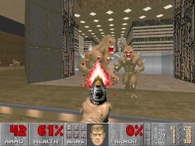
This two issues were solved in a later Id Software´s release: Quake, considered to be one of the first real 3D videogames, and also one of the first games to use a pre-computed lighting model

Let there be light
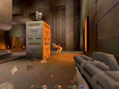
First, a quick look at a Quake screenshot:


[A note for principiants:]

Comparing it with the Doom picture, the first change is that here, everything is 3D. No sprites at all, but polygons, points and textures. And this is crucial, as it makes possible the second change, which is obviously the lighting system. Remember that sprites are just pictures that are copied to the screen when needed, already including their illumination. That´s why they doesn´t work well with other environment lights. Polygons and vertices, unlike them, can hold properties to feed a lighting engine, as position, orientation, etc.

In the screenshot you can see an orange light source coming through the door on the right, lighting the box in the center and the character in the middle. The box also projects a shadow to the floor and there are additional shadows in the walls too. In short, Quake had a very decent lighting model, providing the game with a much more real lighting, and therefore, a better immersion. Let´s see how all this stuff is done...

Vertex lighting. Enough even for quake?

One of the first approaches to 3D lighting models is the so-called Vertex Lighting, which is well covered in this nVidia article. Basically, it computes the amount of light received by every vertex of every polygon that composes a 3D model, and uses that amount of light to modulate the color of the vertex and therefore the interpolated color through the polygon.

It works well for very high detail 3D models, where the distance between vertices is small, and therefore the sampling frequency is high. BUT, for performance reasons, 3D games cannot have an unlimited level of geometry detail. Even more in 1996. The following picture shows an approximation to the level of geometry used in Quake:

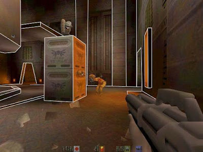
As you can see, it has a VERY LOW level of detail. Take a look at the shadow the box projects to the floor. It is a gradient through the geometry, where no vertex appears, so that gradient cannot be hold by Vertex Lighting.
Even now it´s impossible to use enough detail in geometry to make Vertex Lighting usable as the only lighting model.
So, now what?
The answer is to use some kind of system that allows us to store lighting information in the inner points of a polygon (not only at the vertices), without increasing the real detail of geometry. Think about it as a two dimensional table with numeric values storing the amount of light received by every inner point of the polygon.
Some questions come out quickly now:
1.- How big that table should be?
Of course this comes to a sampling frequency problem: the more samples we take (points per inch, or whatever), the more detail in the lighting.
2.- How do we relate the inner points of the polygon with the entries on the table?
Will see this later.
3.- Will the PC have room for so much information?
Let´s make a quick calculation for Quake: maybe 1000 polygons per scene, with a lighting table of 32x32 samples, makes a total amount of 1.024.000 floats. What is more or less 4 Mb of memory.
Nowadays, it doesn´t look so much, but remember that Quake was released in 1996, when the typical PCs where intel 486 or Pentium in best cases, with a clock frequency between 66 and 133Mhz, and with a system memory of maybe 8Mb or 16Mb. So, wasting one half or a quarter of the total available memory in lighting is definitely not feasible.
4.- Will the PC have enough computing power for that lighting system?
Definitely not. Calculating the lighting for a single point can take a lot of operations, and it would have to be done 1.024.000 times per frame.
Then, how this damn Quake works?
That´s the question. How does a PC like a Pentium 66Mhz handle all this lighting and graphics in realtime?
Easy, it doesn´t.
If you think a little bit, you will realize that though you can move freely through your room, lights normally don´t move, and in most cases, objects neither. So, why not to pre-compute the lighting of static objects just once, storing the results somewhere? That´s what Quake does.
It has a level editor which allows you to place lights through the scene, and calculates the static lighing of the environment offline, storing the results for a later realtime usage.
That saves all the realtime calculations, solving the problem of question #4, but it doesn´t solve the memory problem of question #3, and again it doesn´t explain question #2.
Questions #2 and #3. Lightmaps on the stage
Take a look at the lighting tables which store the results of the offline lighting calculations done by the level editor. Wait a moment... a 2D table storing numeric values... mmmmhhhh... I have seen this before... Digital pictures or Textures are very similar to this stuff: 2D tables of data... And... wait a moment! If I store those results in Textures or digital pictures, instead of simple 2D tables....
Yes, that´s the point. If you store that information in textures, you can:
1.- Use compression algorithms to reduce the amount of memory needed. Lighting will be very similar in many places so block packaging and compression will save A LOT of memory. This helps with the question #3.
2.- You already have a system to relate the inner points of a polygon with the contents of a texture: TEXTURE COORDINATES. This solves question #2.
That´s right. Lightmaps are special textures which store lighting information, instead of the appearance of a base material. Just like this one:
They were widely used in Quake to store lighting and are a great way to add realism to your 3D engine. Since then, Lightmaps are a must in any modern 3D application.
Although there have been some approaches to Dynamic Lightmapping, lightmaps are normally used to store static lighting information only, combined later other kind of lighting that cannot be static, for moving lights or objects: vertex lighting, shadow mapping, shadow volumes, vertex and pixel shaders, etc...

Textures Rock!
Once we have a way to relate points on the surfaces of 3D objects with texels on a texture, we can store any kind of information on them: bumpiness, shininess, shadows, specular components, etc.

Take a look at the following example taken from here (a very good article on shading). This image belongs to the Valve Engine used in games like Half-Life.

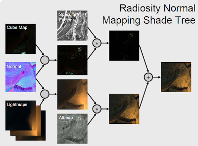
You can see that they use a whole bunch of different textures to store different kind of information about surfaces, getting very good results, as seen in Half-Life 2.
Don´t break the magic
The fight 3D programmers are involved in, since the years of Doom, is nothing more than realism. In other words, don´t break the magic with strange or unaccurate lighting. Try to be accurate and look into the details that make a picture look real. For instance, take a look at this pic:
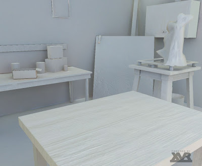
Another example:

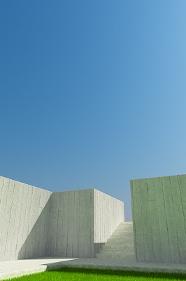
Those pictures use a very simple geometry, and almost no textures... So, what makes them so damn real?
Easy... PHYSICALLY CORRECT LIGHTING
Lighting is everything. It determines the way objects look more than anything else we can use in computer graphics. That images look real because they use a lighting engine with concepts like radiosity or global illumination.
Lighting is not just about finding the amount of light between 0 and 1. A real lighting engine uses photometric lights, with real physical properties, and propagates light correctly through the scene, reflecting and refracting each ray of light. A real amount of light is between -infinity and + infinity, and a real High Dynamic Range display system maps those values to the screen.
The need for a pre-computed illumination model
It´s clear that the next challenge in computer graphics is not realism, but to be able to make all this calculations in realtime. To allow illumination to be really dynamic. With no tricks at all... just real dynamic lighting.
Of course, the amount of calculations to make is huge. So the question is: will we make it in the next few years or will we still need a pre-computed (static) illumination system?
Let´s make a quick assumption. Nowadays, a very good lighting engine like V-Ray can take hours to calculate the illumination of a scene. Let´s say, 10 hours (what is not exagerated at all). We are able to generate a new image every 36.000 seconds.
So, if we want to make those calculations at, maybe, 60 fps (one image every 0.016 secs), we would need a computing power more than 2 million times bigger than the power we have right now, what seems to be a little bit too much. Of course we cannot think the evolution of computing power will be linear, as newer techniques will for sure be discovered, speeding thiings up, but anyway the leap forward is huge and such a thing doesn´t seem to be feasible soon.
So, we will still need pre-computed systems for quite a little bit yet.
Anyway, who knows!